![]()
![]()
![]()
Teachers Introduction Course to LEGO® Mindstorms NXT & EV3
(version 4.6)
UNIT 13. On programing design patterns architecture in NXT and EV3.
The following learning unit explores the main different strategies to write a computer program in the LEGO Mindstorms NXT and EV3 software to control its flow of decisions, especially between sensors and actuators. It is very useful to systematize the known standard design patterns by creating a glossary of the most common programing solutions to solve specific ad hoc problems. Having a checklist of needs and constraints saves a lot of time and helps to better understand, analyze and organize the programing code to get the best solution.
This learning unit is inspired by the LabVIEW Core 1 and Core 2 course manuals.
Unit 13 design pattern 1: Sequential programing, the simple design pattern.
Probably the simplest way we can make a robot do certain actions is to drop the different action blocks in the programing interface, for example to control the motors, one after the other, from left to right and just after the “Start block”, in accordance to the sequence of actions we want the robot to accomplish. As you start dropping the blocks in the programing interface, these connect to each other ensuring the actions to occur sequentially, and executing one block at a time and after the previous block is completed, all the way until the end of the program. This is called the simple design pattern architecture.
Unit 2 “Motors, movements and turns: precise control of the distance moved” strictly shows sequential programing examples.
A little bit of theory
The programing blocks sequence is called “sequence beam” and the NXT programing interface makes an explicit reference to a LEGO Technic beam, as the image below shows.
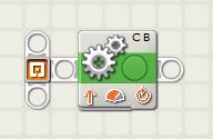
Explicit sequence beam in NXT
To make explicit the sequence beam in EV3 just click in the right button connector of any block and the right block next to it will move to the right making visible the sequence beam. A sequence beam is simply a data wire that ensures the blocks to be executed sequentially from left to right. Without the sequence beam all blocks will be executed at the same time or without knowing the order of execution.
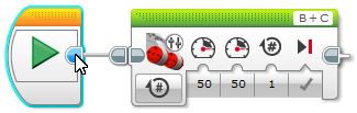
Making explicit the sequence beam in EV3
In general most programs can be designed sequentially, and this is very practical because we tend to think sequentially, although most of the time events do not occur sequentially. What will happen if some actions need to be repeated? What will happen if some actions need to be taken but we do not know when or their order of execution? What will happen if some actions need to be taken under different specific conditons? What about if we need to stop the program under a very specific circumstance?
For example, let’s imagine a robot that goes straight but needs to sort obstacles and beep at any line and go over it, until the line is red where it needs to stop. We do not know whether the obstacle will be before the intersection or after it and how many obstacles the robot will encounter. So how will we program the robot strictly using a sequential pattern? We cannot, unless we know exactly how many obstacles and lines the challenge has and in what order they are placed. If either one obstacle or one line is changed the program will not work anymore. We need to use a more complex programing pattern architecture.
Unit 13 design pattern 2: Loop programing, the general design pattern.
When we have to execute a series of actions that repeat over time following a specific pattern, we need a more complex structure than the simple design pattern. We need to introduce a loop in the so called general design pattern architecture. In the general design pattern architecture, the program usually starts with some initial actions, a loop that contains the main program, and some closing actions before the end of the program. Interestingly, many times the main program of the loop is just a simple sequential program, but if we need to execute more complex tasks, the main program can be much more complex than this. The following images show the general design pattern architecture.
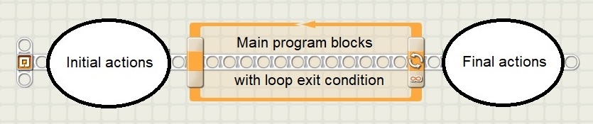
General design pattern architecture in NXT
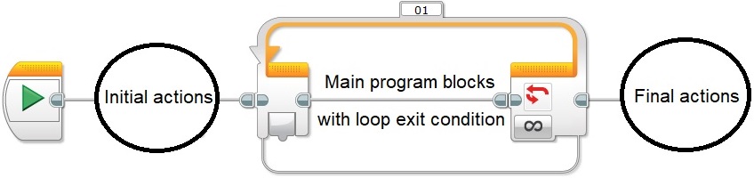
General design pattern architecture in EV3
With the general design pattern we can easily repeat many actions at each loop iteration, even sequentially, or establishing an order of priority even without knowing how they will occur in reality and while the program runs. For example, in the previous example, we can assume that, at each loop iteration, the robot will need first to check for the obstacle and if there is no obstacle, check for the line and beep if it is not red and continue, or stop if it is red and get out of the loop. All these three actions will execute very fast so we can think about them iteratively. Iterative thinking is not always obvious and intuitive and students need to learn it. In addition, when several actions repeat indefinitely, iteration can be complicated with recursion. Recursive thinking is a little bit more complex than iterative thinking. In our case we have several conditions and recursion allows us to go systematically through all the possible conditions and find the one that needs to be triggered to accomplish the appropriate actions.
In our example we can write the code as shown in the program schematics below.
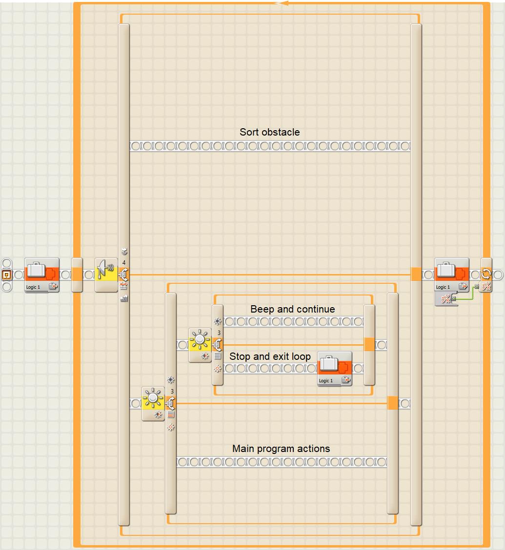
Iterative and recursive loop programing in NXT
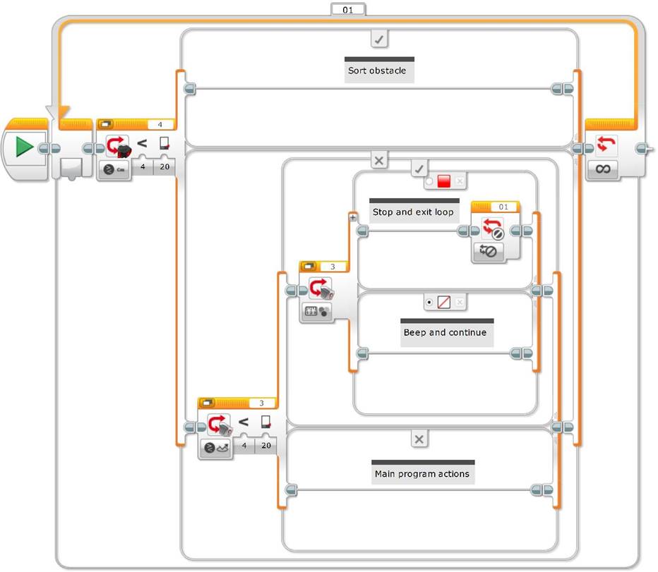
Iterative and recursive loop programing in EV3
The students need to understand that the loop is executed so fast that the main program actions –in the last branch of the nested switches– will only execute whenever no other conditions are met in the same loop iteration. In addition, one should be aware that eventhough in most cases changing the recursive conditions sequential order will not affect the robot behavior, this might not always be the case.
The end of Unit 3 “Sensors, conditions and loops: decision-making” shows the first example of loop programing with the general design pattern. Unit 5 “Advanced switches and loops: movement logic and decision-making in function of a combination of sensors” has other loop programing examples and introduces the two-steps simple line follower that at the end is mixed with sequential programing. Unit 6 “Inside a two-step simple line follower: data logging and experiments” has examples of initialization and finalization actions which clearly illustrate these concepts (by initializing and closing variables and files, and stopping the motors when exiting the loop).
What will happen if we need to run at the same time different repeated actions but at different execution rates? It is not enough to split the sequence beam inside the main loop because the main loop will not repeat until the longest split sequence is finished! The solution is to run different loops in parallel.
Unit 13 design pattern 3: The parallel loop design pattern.
Let’s imagine that in our example, in addition to all the actions, we want the robot move a hand according to a specific behaviour at the same time. Clearly these hand actions will need to run independently and at a very different rate than the main robot program. The only way we can accomplish this is by running at the same time two parallel loops, one for the main program and another one for the hand. The parallel loop design pattern architecture is another basic programing strategy that allows controlling simultaneously different independent tasks. The following images show the basic elements of the parallel loop design pattern architecture.
Parallel loop design pattern architecture in NXT
Parallel loop design pattern architecture in EV3
But now the problem is: how can we control, coordinate and communicate the different loops of the parallel loop design pattern? Can we use data wires? The answer is not at all, because data wires will not allow the loops to run in parallel. In fact, a block connected to a data wire will not execute until the block connected at the left of this wire is executed. This is why we use the sequence beam as a very special data wire that ensures the sequential execution of the program blocks. The answer is: we need to use variables.
Unit 13 design pattern 4: Parallel loops control, the master and slave design pattern.
As you might have anticipated in the previous example, we might need to coordinate the behavior of the hand with the main loop actions, or just stop the hand loop when the robot encounters the red line. How can we accomplish this communication between the main program loop, called the master loop, and our hand loop, called the slave loop? We need to use a variable that the main loop will set to True just before its exit and which will be iteratively read by the slave loop causing its exit whenever it is True. Alternatively in EV3 we can use the Interrupt Block which will be called for both loops inside the master loop to stop the program. In our example, the interrupt blocks will be called when the red line is detected inside the master loop.
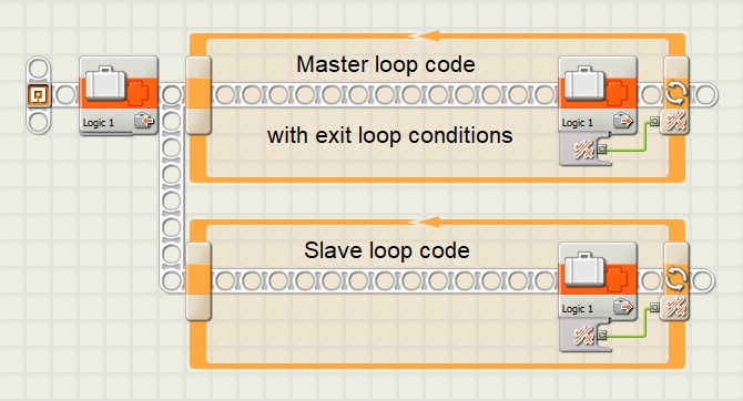
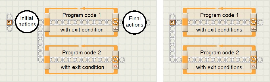
Master and Slave design pattern architecture with only exit condition in NXT
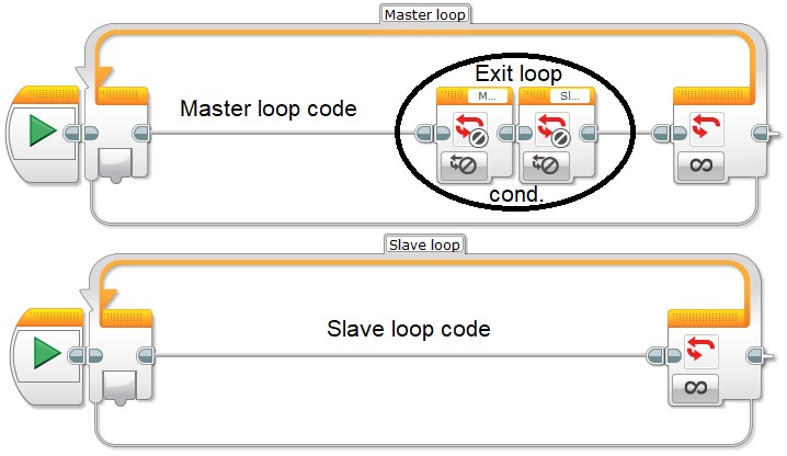
Master and Slave design pattern architecture with only exit condition in EV3
In the more general case, the master and slave design pattern architecture has several parallel loops running or executing tasks at different speeds. One loop acts as the master and the others as the slaves. The master loop controls all the slave loops and communicates with them using variables. It is important that only one master loop sets the variables to avoid variable state contradictions, called race conditions, which can be often difficult to debug and find inside the code. A race condition might occur when different parts of the program attempt to set the variables at the same time.
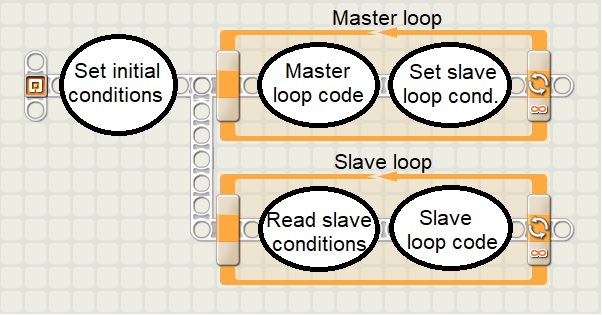
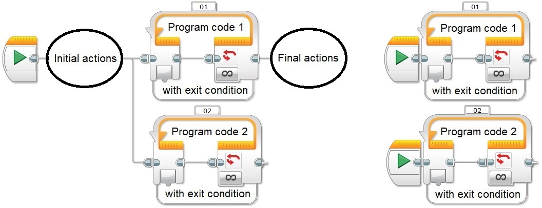
Master and Slave design pattern architecture in NXT
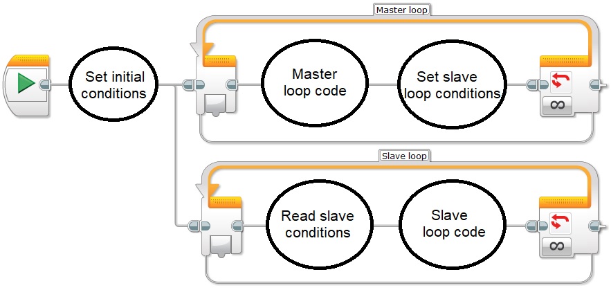
Master and Slave design pattern architecture in EV3
As you might have realized, one problem of the master and slave design pattern architecture relies in the fact that if the execution speed of the slave loops is slower than the one of the master loop some variable states might be missed during the execution of the program. So at design time one must be very aware of this issue.
Let’s consider the following example: imagine we want to build a car proximity sensor for our robot. We need to implement a beep sound in function of obstacle proximity in such a way that the closer the object is the faster the beeps will repeat. How will we program this functionality? Clearly the beep repetition speed will have to be proportional to the obstacle proximity. In addition, meanwhile the robot executes its main program, the beeper proximity function will have to run in parallel and at its own speed. Since the main program reads either an ultrasonic or an infrared sensor measuring proximity, the best solution is to set a numeric variable with the distance, in the main program inside the master loop, and read this variable in the proximity loop, the slave loop, as shown below.
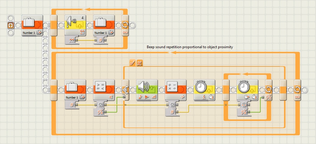
Implementation of an obstacle proximity sensor in NXT
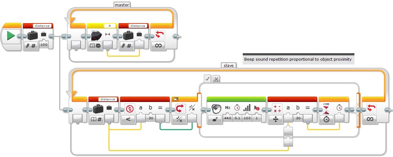
Implementation of an obstacle proximity sensor in EV3
In this example, the main program only reads the obstacle distance with an ultrasonic or infrared proximity sensor, so it is very simple, later on we will add it to our previous robot example. The question is: will this program work? The answer is: apparently yes and quite well! If we analyze the two loops what can we say about their execution speeds? Although reading a sensor takes some time, like in this example’s master loop, playing a sound and waiting to repeat the sound, in the slave loop, are probably much longer to execute. So why does the program seem to work so well? Although that some distance values set by the master loop are perhaps missed by the slave loop, because it will probably run slower, the beeps seem to be quite proportional to the obstacle distance anyway. In this case, it is not this crucial that the slave loop will run slower than the master because the slave loop will eventually catch up, except if the movement of the obstacle or the robot is not linear, or it is too fast.
Let’s try now to integrate the previous beeper function into our main robot example, as shown below.
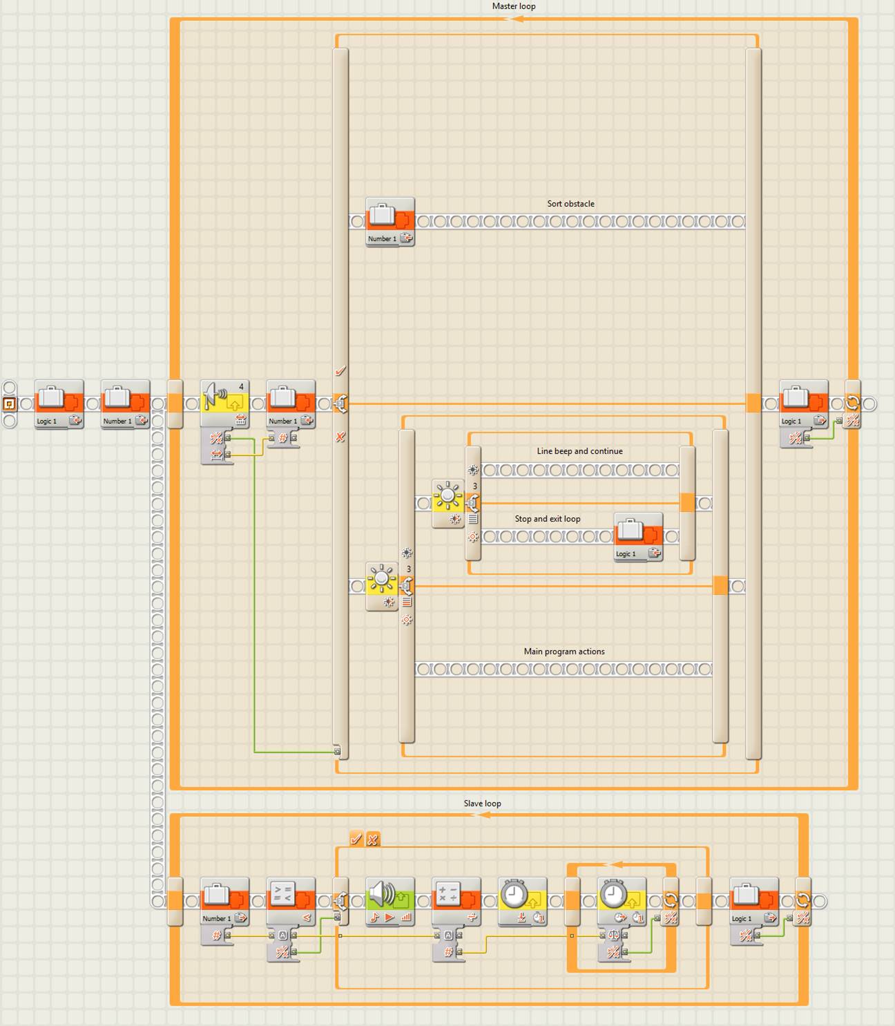
Implementation of an obstacle proximity sensor within the robot main example in NXT
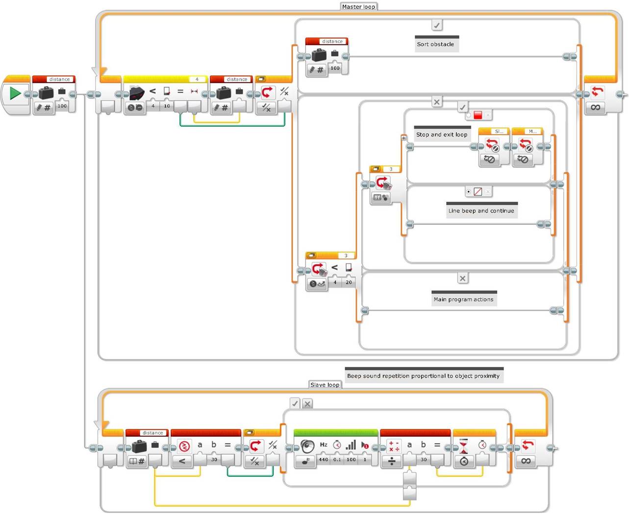
Implementation of an obstacle proximity sensor within the robot main example in EV3
As you can see in the previous code, this time the master loop might take slightly more time to execute than the slave loop, especially when executing the “Sort obstacle” and the “Line beep and continue” branches of the switches. Probably the “Main program actions” branch will be faster to execute than the rest, and even faster than the slave loop, if it only starts a motor or contains a line following algorithm.
What will happen with the proximity beeper when the robot encounters an obstacle and the distance is close enough to trigger the “Sort obstacle” branch? For how long will the beeper sound? Since the variable will be set for a distance between the threshold to sort the obstacle and the one to start beeping, it will beep proportionally to that distance until the obstacle is sorted, meaning that it will beep until its master loop branch execution is complete and the next loop iteration is entered again. If you want to avoid the beeper, because the robot already knows it has to sort the obstacle, what can you do? The answer is, just before sorting the obstacle, set the variable to a bigger number, as we do at the beginning of the program, to avoid an initial beep as a result of a numeric variable defaulting to “0”, if we do not initially set it.
Unit 10 “To light or not to light: how to use the legacy lamp in EV3” has very interesting examples of how to use the master and slave design pattern and addresses very specifically the problem of synchronizing the lamps’ blinking by synchronizing the loops of each lamp.
Unit 12 “How to toggle a motor on/off with a touch sensor” shows other examples of how to use the master and slave design pattern.
Unit 13 design pattern 5: State machine design pattern.
As seen in the sequential programing style, the blocks with decisions and actions are programed sequentially and following a specific order, for example, following the order in which the robot encounters the line intersections, following a specific reading order of the different robot’s sensors, and finally taking actions in function of a specific sequence of decisions. We have seen that in Mindstorms NXT and in EV3 the sequence beam establishes the program blocks execution order, from left to right. The sequential programing is one of the most common and often more obvious programing styles, because if the program is not very complex, you can write it without any planning, but it is not always the most efficient, most flexible or most understandable style in the long run.
For example:
- What happens if we have to change the order of intersections or the order of the sequence?
- What happens if we have to repeat several times one or several sequence components, for example, to repeat several turns to one side, or to go forward on several different color lines of the path?
- What happens if we have to execute a sequence part only when a specific condition is met, for example, if we have to add an ultrasonic sensor in one side to make the robot choose the right side of the obstacle to sort it, or follow a wall when there is no path?
- What happens if we want to stop immediately the execution of the program when a specific condition is met and we do not want to wait until the rest of the sequence is finished?
How can we improve the sequential programing to make it more functional, more compact and even better understandable and easier to debug? The answer is: by using the state machine design pattern architecture.
A little bit of theory
The state machine programing model is a very common and useful model that allows implementing any relatively complex algorithm that can be represented by a data flow diagram with its decisions making processes and its resulting actions.
A state machine (or finite state machine) is based on a series of states with a transition function which sets the next state to take. Each state contains an action to take and a transition code that calls the next state. Often the programs or applications require an initialization state, followed by a default state –where for example, the sensors are read to make decisions and to call other states or take different actions– and finally, it can have a closing state to carry out cleaning actions before finalizing the program.
In Mindstorms NXT and EV3 we can create the state machine design pattern as a modification of the general design pattern by adding a case structure to its loop and using a variable. In NXT or EV3 the state machine design pattern has a loop, a case structure or multiple switch –where each case represents a state–, a variable to store the transition information between states at every iteration of the loop, a functionality code for each state and a transition code that determines the next program state. To get out of the loop, in NXT we need to use a logical loop and a second logical variable, initialized to False, which will only be set to True in the finalization state to get out of the program. In EV3 the loop can be set to unlimited and we just need to add the “Loop Interrupt” block in the finalization state. Finally, we can define the state machine default case to the initialization case. In the following example, the state machine structure has 4 cases represented by the 4 case structure tabs: “Initialization”, “State 1”, “State 2” and “Finalization”.
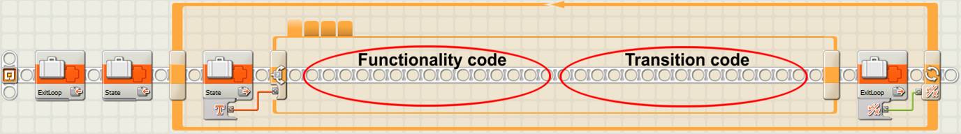
Basic elements of the state machine design pattern in NXT
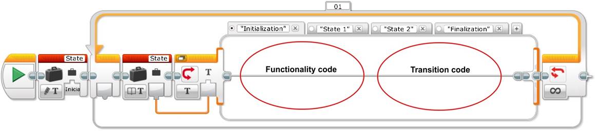
Basic elements of the state machine design pattern in EV3
How can we implement the transitions of a state machine? There are three different types of transitions control:
· The simplest one is the individual case transiton, which can be useful for a default transition, for example. The simplest contents of this code will be a variable pointing to the default actions or configuration.
· The next transition control is the transition between two states. The contents of this transition will be a functionality code based on a simple switch. The two states transition control is useful if we only have two possible cases, but it is difficult to adapt to future changes and limits the code scalability.
· The third transition control is the transition between two or more states. The most appropriate soluton is to use a multiple swith or case structure. One advantage of the case structure is that it self documents the code making it very readable. Each case corresponds to a value of the state machine variable. It is also very scalable and, meanwhile the application grows, it is very easy to add transitions to a specific state by adding more cases to that state case structure. One disadvantage of the case structure is that you cannot see all the transition functionality code at once, as we will see in the next examples.
If we go back to our robot example, how can we rewrite the code to use a state machine design pattern instead of the general design pattern? Before writing the program code, let’s draw the Data Flow Diagram of our example. Usually, to draw the data flow diagram of a program before starting its coding is very useful because it helps understanding the problem and saves a lot of program design time and debugging.
A little bit of theory
When we write a program we do not usually start writing the code directly, we need a minimum planning, especially if the program is a little bit complex. A data flow diagram (DFD) is a graphic representation of the data flow through an information system that can be also used to visualize the data processing. In our case we can use it to visualize and graphically differenciate the program parts that read data, the parts that make decisions from reading the data, the parts that do the actions according to each decision and the program’s data flow that connects all the previous parts. If a data flow diagram is well done writing the code can be very simple.
Data flow diagrams can be represented in several ways and with more or less detail. In our case, we will represent the actions –and/or subprograms, which can also be represented with sub-DFDs– with a rectangle, the decisions with a diamond and the data flow between decisions and actions with an arrow. Every time a decision is made we will inform the arrow that goes out from the diamond about whether the decision corresponds to a “yes” or a “no”.
The following image shows the data flow diagram of our robot example.
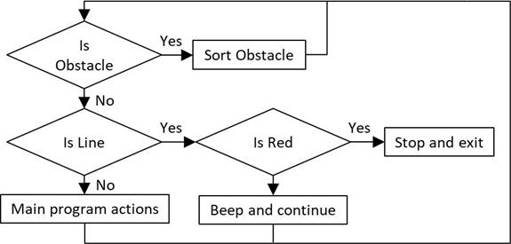
Data Flow Diagram of our robot example
The following images show our robot example program using a state machine design pattern with a multiple switch transition control.
“ReadSensors” case of the robot example program using a state machine
design pattern with a multiple switch transition control in NXT
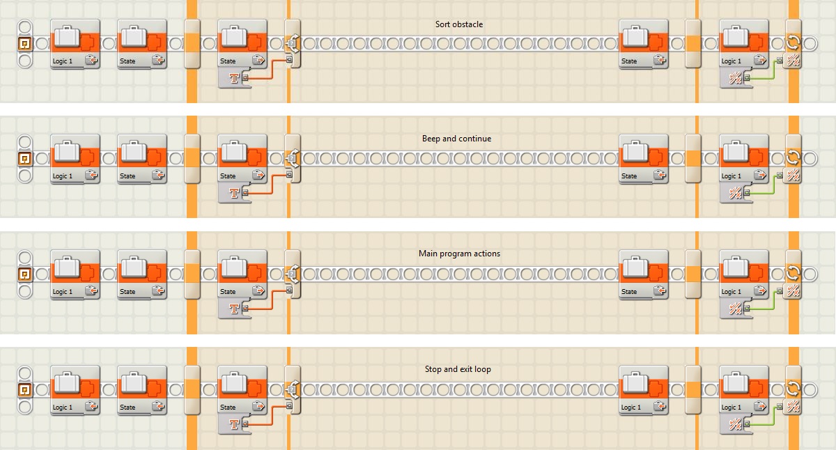
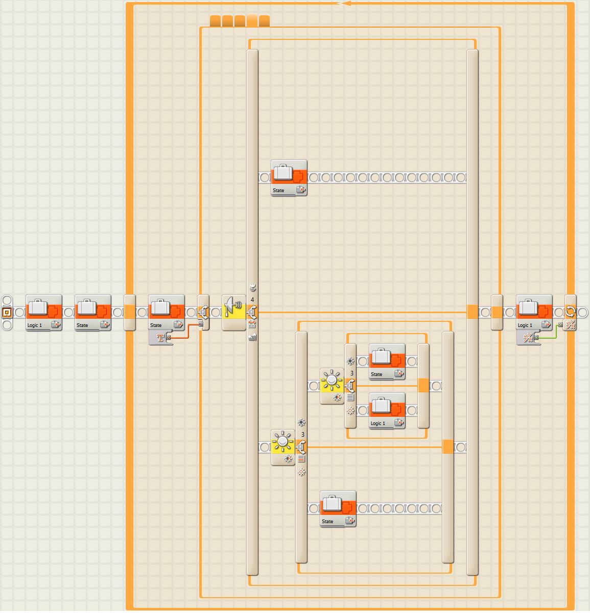
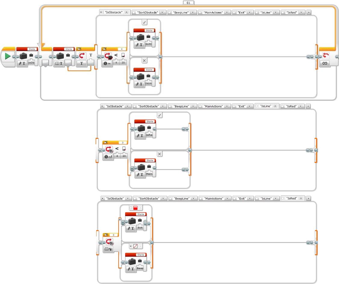
Rest of cases of the robot example program using a state machine design pattern in EV3
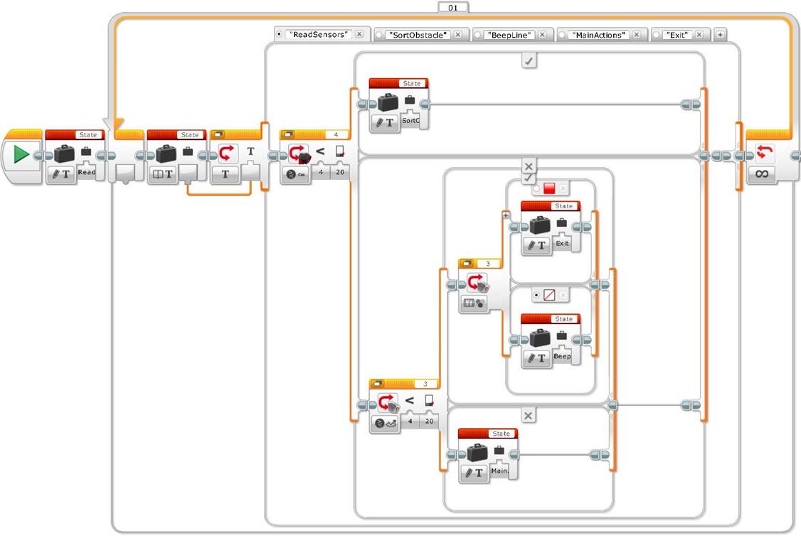
“ReadSensors” case of the robot example program using a state machine
design pattern with a multiple switch transition control in EV3
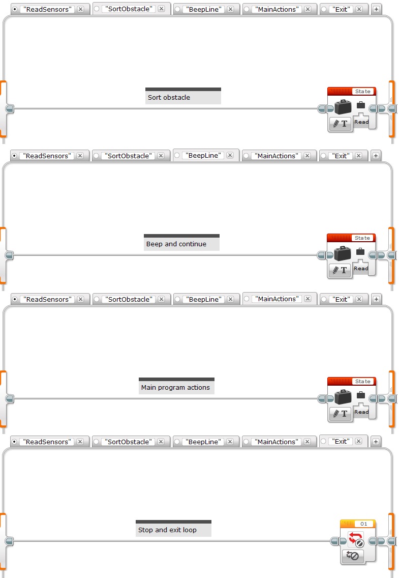
Rest of cases of the robot example program using a state machine design pattern in EV3
The first important thing to notice in the previous example code is that the first case “ReadSensors” encapsulates all the decisions of the state machine program, and it is programed sequentially by nesting three switches. This is very useful because we can easily understand the flow of decisions. The switches associated to the sensors represent the functionality code and the variables the transition code. Notice how each variable points to a different “action” case. The rest of the cases represent the different actions of the state machine. In these cases, the functionality code is left out (it is just represented by a text) and the transition code is represented by the variable pointing to “ReadSensors” in all cases, except for the “Exit” case.
Tip: As a good programing style practice, never mix decisions and actions in the same state, use different states to separate them. This is especially useful when different decisions trigger same actions because it avoids repeating code.
Is there any limitation to the previous code? If we want to modify the program to add more transitions or to change the priority order of decisions, since the decision making case “ReadSensors” is sequentially programed, we will have to modify it by adding more switch branches or change it completely to alter the decision priorities, as pointed before. Of course we will also have to add the corresponding actions to the state machine. Is there a strategy to minimize changes when adding new functionalities? The solution is to split the decision making case in function to all the different decisions to make, as shown below.
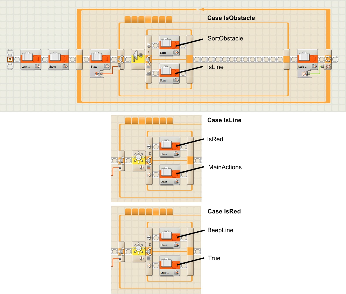
More flexible alternative of the robot example program using a state
machine design pattern with switches transition control in NXT
More flexible alternative of the robot example program using a state
machine design pattern with switches transition control in EV3
As shown in this alternative, which uses the transition between two states for the state machine design pattern transition control strategy for our example, three cases containing a switch are created, one for each sensor decision. The action cases are kept the same as before, except for the variables which are modified accordingly (actually calling “IsObstacle” case instead of “ReadSensors”). Although maybe this program is a little bit more complex to follow, it is though much more flexible. For example, we just need to change the variables to change the decisions’ priority order, or if we need to add more transitions or functionalities, we just have to add the corresponding decisions and actions without having to modify the rest of the code.
A simple example of a transition between more than two cases can be a color sensor case structure with more than two colors. Each case will contain the variable pointing to that case specific transition. In a more general situation, the functionality code will return a value that will be connected to a case structure. As an example, you can see the initialization state, or also the intersections management state, of the state machine for the line follower of Unit 9 “From sequential programing to state machine: the four step simple line follower with two light or color sensors”. In this example the transition code has the variable connected to a four cases structure in both states.
Finally, we can mix all the different design pattern architectures to better suit our programing needs. The power of this glossary is to allow us simplify and structure the programing design process by helping us detect the different functionalities we need to include in the program before starting coding.
One problem of the state machine design pattern is that we need to avoid setting two states at the same time, also called a race condition, to avoid missing the execution of some states encapsulated by the variable, for example, when mixing this pattern with the parallel loop or the master and slave design pattern. Avoiding states can generate very difficult errors to debug because they might be very difficult to reproduce.
Acquired knowledge: With this unit students will learn how to program in more sophisticated ways recognizing and systematizing the needs of their programs. They will also learn how to draw data flow diagrams to plan before coding, and how to mix the different techniques and design pattern architectures to write better, simpler, more compact, easier to debug and more efficient programs.
You can also find this learning unit at the legoengineering.com webpage.
![]()
![]()
![]()
![]()