![]()
![]()
![]()
Teachers Introduction Course to LEGO® Mindstorms NXT & EV3
(version 4.6)
UNIT 12. How to toggle a motor on/off with a touch sensor.
 Starting with a simple challenge involving a touch
sensor and a motor, this learning sequence introduces a range of programming
techniques to show how to control an actuator with sensors using flow control
structures.
Starting with a simple challenge involving a touch
sensor and a motor, this learning sequence introduces a range of programming
techniques to show how to control an actuator with sensors using flow control
structures.
These programming structures include wait blocks, switches, loops, flags, and the master/slave design pattern. In addition, it also shows how to use variables, user blocks with arguments, arrays and how to operate with them.
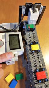
The right image shows a color counter machine with an EV3 Touch sensor.
Unit 12 exercise 1: Turn a motor ON with a Touch sensor.
The touch sensor is the simplest sensor in the LEGO Mindstorms platform. It gives a true value if it is pressed and false if it is not. In addition, you can configure the touch sensor to give a true value if it has been bumped, that is if the sensor has been pressed then released.
How could you program a motor to start when a touch sensor is pressed? The simplest way is to use a Wait block configured to use a Touch sensor as shown in the following image.
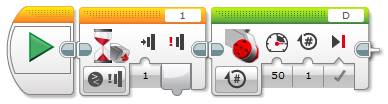
Wait until the Touch sensor is pressed then start a Motor
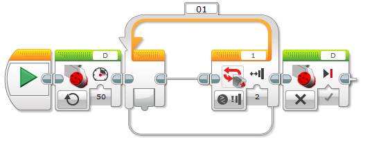
What are the limitations of the previous program? As intended, the motor will only start after the Touch sensor is pressed. It will, however, only run for one rotation. What if you want to make the motor run continuously? Some students might say that you only need to configure the Motor block to turn the motor “On” instead of “On for Rotations”. If you try this, you will see that the motor does not even start! Why? Because the program ends after the Motor block and when a program ends, all motors are turned off. How do you have to modify the program to make the motor run forever? One option is to put the Motor block inside a Loop set to “Unlimited”. For example:
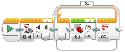
Wait until the Touch sensor is pressed then run a Motor forever
When will the motor stop in the previous program? Either when you will stop it manually or when the brick runs out of battery.
Unit 12 exercise 2: Turn a motor ON and OFF with a Touch sensor.
How can you turn the Motor On and Off using the Touch sensor, for example, to start and stop it whenever you want? How will you modify the previous exercise to accomplish this?
Some students might realize that after waiting for the Touch sensor to start the motor, you can wait again to stop it, because the actions are sequential, as shown below.
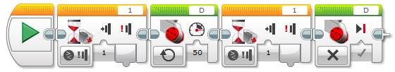
Wait until the Touch sensor is pressed to run a Motor and wait again to stop it
After the first time the Touch sensor is pressed, the Motor will start and the program will wait until the sensor is pressed again to stop it. But does the program work? Sometimes it works, but not consistently. Why not? The program runs so fast that while you are still pressing the touch sensor it will move through the second Wait block and therefore stop the motor. As a result, you need to press and release the touch sensor extremely quickly (or be very lucky), to make the code work. How can we solve this problem? We need to configure the Wait block to use the “Bumped” setting.
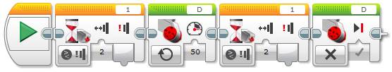
Wait until the Touch sensor is bumped to run a Motor and wait again to stop it
What if you want to restart the motor by pressing the touch sensor again? (without having to restart the program). The solution is to put the previous code inside an Unlimited Loop.

Repeatedly turn a motor On and Off using a Touch sensor
At this point it might be interesting to ask the students whether we can get the same or similar results using a Switch block instead of a Wait block. It is a nice opportunity to think about the differences between these programing structures.

Turning a motor On and Off using a Touch Switch block
What are the main differences between this program and the previous one? With this version we need to keep the touch sensor pressed in to stop the motor. In addition, the motor will start as soon as the program starts, unless the touch sensor is pressed in. Keeping the sensor pressed to stop the motor (or running it if we invert the branches of the switch) might be a requirement for some specific scenarios, but the previous solution using Wait blocks might be more convenient for simple examples. Is there any advantage of this solution compared to the one using Wait blocks? This solution uses one less block and does not repeat any block.
Unit 12 exercise 3: Turn a motor ON and OFF using a Touch Switch and a Loop.
How can we obtain the same functionality of the Wait block solution using a Switch block? The idea is that every time the Touch sensor sensor is bumped (i.e. pressed and released), the motor will alternate between on or off. In the following same code, the logic variable flag alternates between true and false. Its value is then used by a Switch block to determine whether to turn a motor on or off. We use a logic variable because we only have two states (on and off), but we could use another type of variable if we had more than two states.
Turning a motor On and Off with the Touch sensor using a Variable and a Switch block
Although this solution is more complex than the one using a sequence of two wait blocks, it is a much more versatile approach. It still has a significant problem though. Imagine that you want to build a sorter machine and that you want it to show a message on the EV3 brick’s screen about the sorted item, or run specific code depending on the sorted item. Not only does the motor need to run but also several actions might need to be executed, thus making the branch of the Switch take significantly more time to complete. And if we try to stop the motor by pressing the Touch sensor, we will have to wait until the branch is completed. How can we solve this problem? One approach is by using the Master/Slave design pattern architecture…
A little bit of theory
We have addressed this programing technique in the “To light or not to light” unit 10.
In the following example, the master loop uses a logic variable called “Flag” to instruct the slave motor loop to turn the motor on or off.

Turning a motor On and Off with the Touch sensor using the Master/Slave design pattern
Unit 12 exercise 4: Turn a motor ON and OFF with the Touch sensor, and stop the program using another sensor.
Let us build on the idea that the motor you are turning on and off is part of a color sorting machine. As a safety measure, you would like the motor to stop if the Color sensor detects no color (i.e. there are no more items to sort). Or possibly you want the program to stop completely.
In the first example, the one that uses Wait blocks, how can the program “wait until EITHER the Touch sensor is pressed OR the Color sensor does not detect any color to stop the motor”? Since a Wait block can only be associated to one sensor, how can we solve the problem?
Tip: As we have seen in “How to wait for one or more sensor conditions” unit 11, a Wait block is just the implementation of an empty loop associated to a sensor.
Implementation of the Wait block associated to the Touch sensor using an empty Loop
The answer is, make explicit the loop and associate it to both sensors, as shown below.
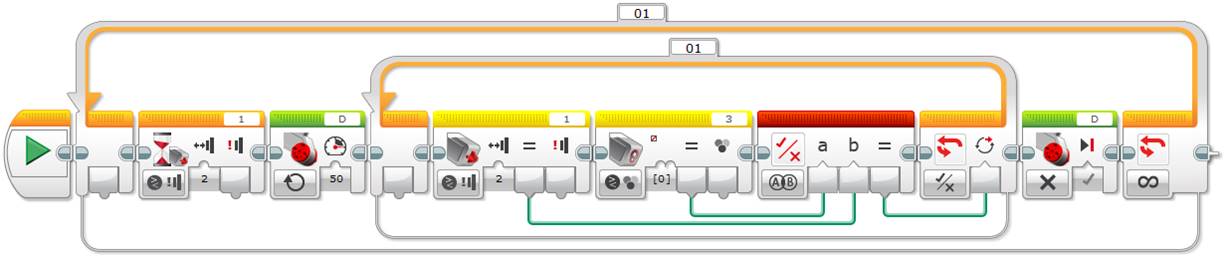
Turning a motor On or Off using a Touch and a Color sensor, using an empty Loop
As discussed before, this program will work fine because the actions, running or stopping the motor, execute quickly, but if we need to execute longer and more time consuming program sequences, we will need a better approach.
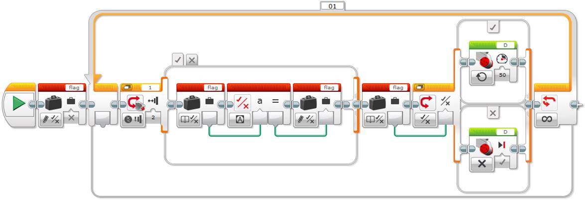
What is a better solution? One approach is to modify the master loop of the Master/Slave design pattern solution as shown below.
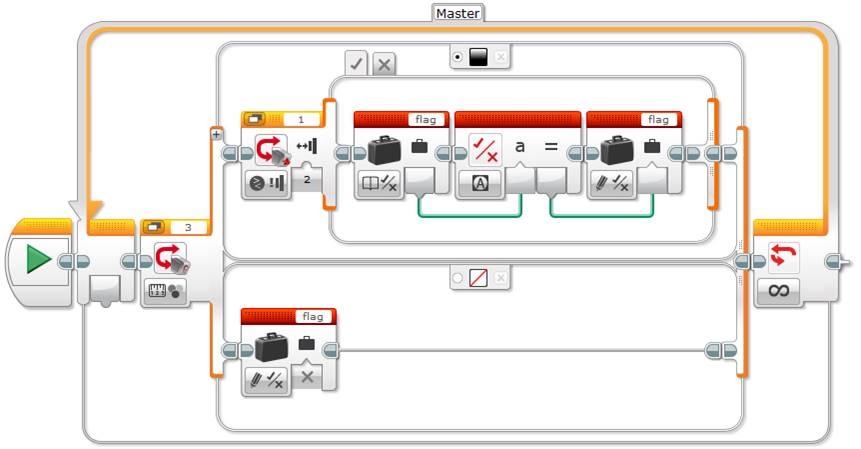
If no colour is detected set the flag to false (i.e. stop the motor) in the Master loop, otherwise toggle the flag if the Touch sensor is bumped
Note that to stop the program, you could use Loop Interrupt blocks, making sure that the motor, or any part of the main program in the Slave Loop, is stopped first.
Another solution is to run different sequences in parallel and use variables to control the flow of the program:
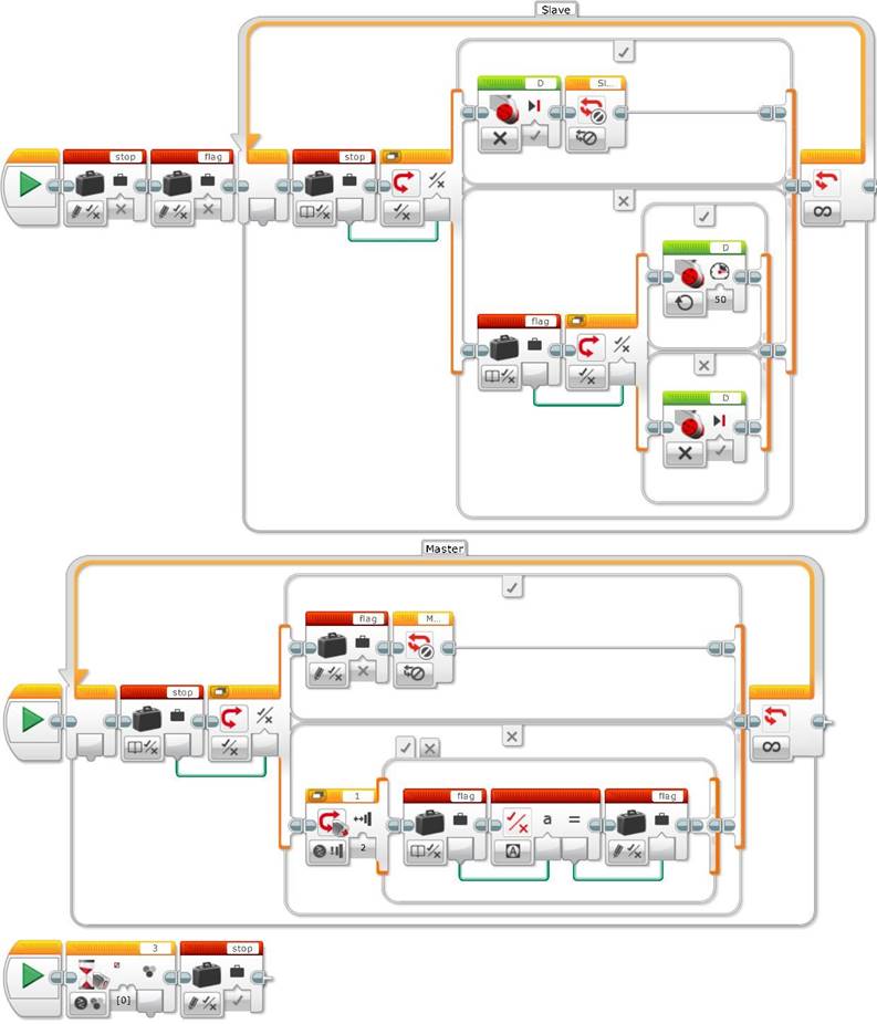
A new parallel sequence stops the Master and the Slave Loops if no color is detected using the new logic variable “stop”
You might need to add specific code in each of the “True” branches of the logic Switches connected to the “stop” variable before exiting the Master and Slave loops.
Since the master loop contains several parallell sequences to control the different processes that occur at the same time, we should be very careful to avoid a race condition, as we will see in the next exercise. A race condition can occur when different parts of the master loop program try to set the slave loop variable at the same time. See “To light or not to light” unit 10 for more about race conditions.
Unit 12 exercise 5: Turn a motor ON and OFF using the Touch sensor and run specific code according to various conditions.
As a final exercise, and to really grasp the power of the Master/Slave design pattern, we will build on the last example from the previous exercise to add the following functions to our color sorting machine.
1. Count the sorted items by color (blue, green, yellow, and red).
2. Display the count for each color on the EV3 brick screen.
3. Pause/unpause the machine if the Touch sensor is pressed.
4. Stop the machine if EITHER no color is detected in a reasonable amount of time OR one of the sorted colors reaches a maximum number.
Note that counting items is relatively fast, but displaying a message in the brick screen long enough for someone to read it requires more time than the other tasks. In addition, while a message is shown, the sorter machine might encounter more items and eventually reach the maximum number of sorted items for one color.
How can we implement these functions? Do we need to change the whole previous program or just a part of it? We just need to change the last branch of the previous program. We will add a new loop to that sequence called “MasterColor”.
Let us address the new functions one by one.
Unit 12 exercise 5.1: Count the sorted items by color.
To count each of the different colors, we need somewhere to store the information. The most efficient solution is to store the count for each color in a numeric array. In this example, we are going to count blue, green, yellow, and red, so let us call the numeric array “SortedBGYR”.
We also need a variable, “ArrayIndex”, to store the index of the array corresponding to the color detected by the Switch block. For example:
· Blue => 0
· Green => 1
· Yellow => 2
· Red => 3
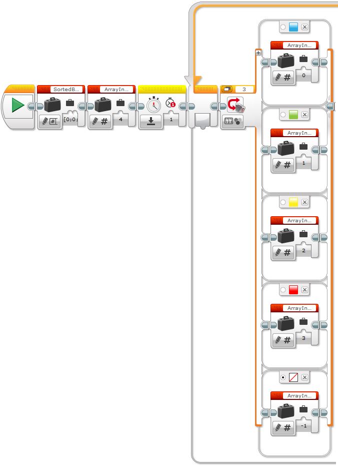
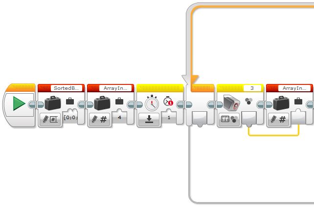
Initialize the variables, reset the timer, and set the value of ArrayIndex according to the color
Note that if no color is detected ArrayIndex is set to -1. This is also the default case. As a result, any color that is not either blue, green, yellow, or red will set ArrayIndex to -1 as well. In addition, before entering the loop, the two variables are initialized, SortedBGYR and ArrayIndex, as well as the timer.
A little bit of theory
A switch with multiple branches is called a Case Structure and in fact a two-branch switch is the simplest case structure. As our above example shows, the Switch associated to the Color sensor has 5 branches, one for each color of the item we want to count. In the EV3 software, inside the switch each color is internally represented by an integer number from 0 (no color) to 7 (black), but the user does not necessarily need to be aware of this internal representation because every time you need to pick a color, the interface shows a menu with all of them, as shown in the following screen capture.
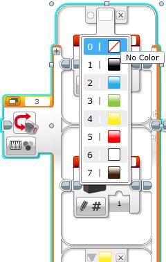
The color indexes of a Color Switch block
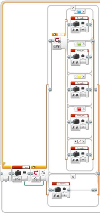
On the other hand, the first item of a number array is “0”. So since our ArrayIndex variable will store the color number, is there a simple way to fill our ArrayIndex variable? If we want to use all the 7 possible colors of the Color Switch, there is no need to use a Switch block at all. Instead we could use a Color Sensor block and connect the Color output plug to the ArrayIndex variable directly, as shown in the image below.
Solution where the Color sensor output updates the ArrayIndex variable directly
Next, we feed the value of ArrayIndex into a Switch block or Case Structure.
If ArrayIndex is -1, we will check the timer and, if necessary, stop the sorter machine, display the message “EXIT”, and set the brick status light to blink red.
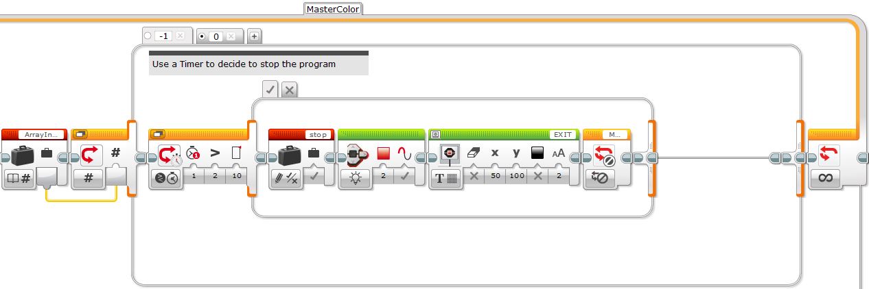
Case -1: If no color has been detected, exit the program
Note the use of a Switch Timer block set to 10 seconds to allow time for the next color to be detected. If no color has been detected with 10 seconds, the program is stopped. The false case is empty.
Also, note that if you store the color directly to the ArrayIndex variable, the previous case number will have to be “0” instead of “-1”. In addition the default case will have to be a number other than “0”.
If ArrayIndex is any number other than “-1” (in our example 0, 1, 2 or 3) the appropriate counter will be incremented.
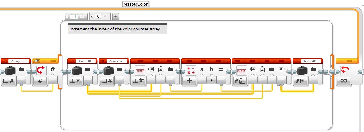
Case 0 (default): Increase the count for the specified color
What will happen if a unexpected color is detected? As mentioned before, the default case of the Color sensor Switch (in our case “No Color”) will be called and the sorter machine will treat this case as if no item is detected. If this occurs for more than 10 seconds the program will exit.
Unit 12 exercise 5.2: Display the count for each color on the EV3 brick screen.
The next step is to display the contents of the array on the EV3 brick screen.
One option is to create a My Block (also called user block) that takes the array you want to print as its input and goes through the different indexes to display them on the brick’s screen. Note that only the first Display block clears the screen.
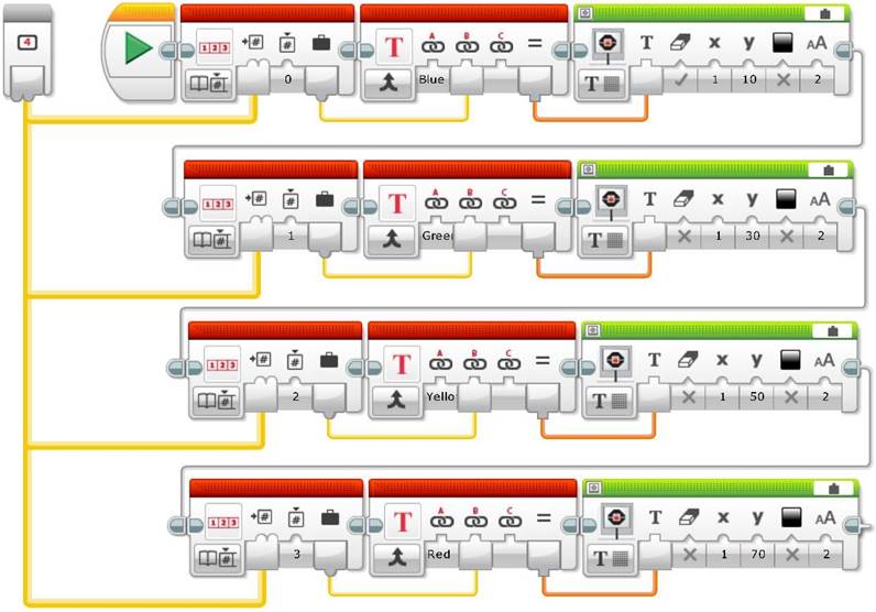
PrintArrayBGYR: A My Block using a numeric array as an input
In the case you want to use all the colors detected by the Color sensor, then you will have to add the missing colors and change the color indexes to match those of the internal representation.
Add the My Block, PrintArrayBGYR, into the end of the loop.
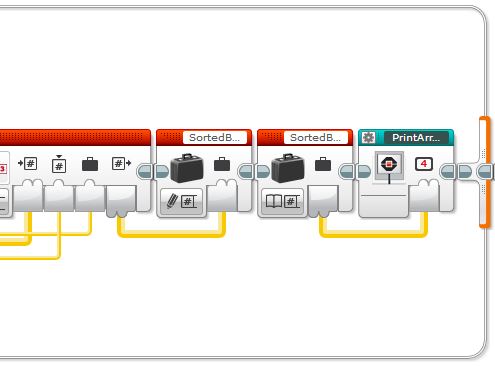
My Block PrintArrayBGYR added to the end of the program
This approach makes the main program much easier to read, and helps with debugging. It also means that this code can be used in different places throughout the main program. For example, we could also use it to initialize the brick screen message.
My Block PrintArrayBGYR added to the start of the program
Unit 12 exercise 5.3: Pause/unpause the machine when the Touch sensor is pressed.
Next, we incorporate the flag variable from Exercise 4 to pause/unpause the machine when the Touch sensor is pressed.
We will add a Logic Switch block to the start of the loop to set ArrayIndex to -2 if the flag has been set to false.
If the flag is false, set ArrayIndex to -2, otherwise set it as before
We also need to add a -2 case to the final Switch block or Case Structure to display the “PAUSE” message and set the brick status light orange.
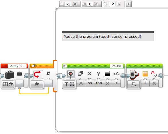
Display the “PAUSE” message and set the brick status light orange
Unit 12 exercise 5.4: Stop the machine.
Finally, we need to stop the machine when either no color is detected or one of the sorted colors reaches a maximum number. The example below shows a simple strategy for stopping the machine when the number of items reaches five.
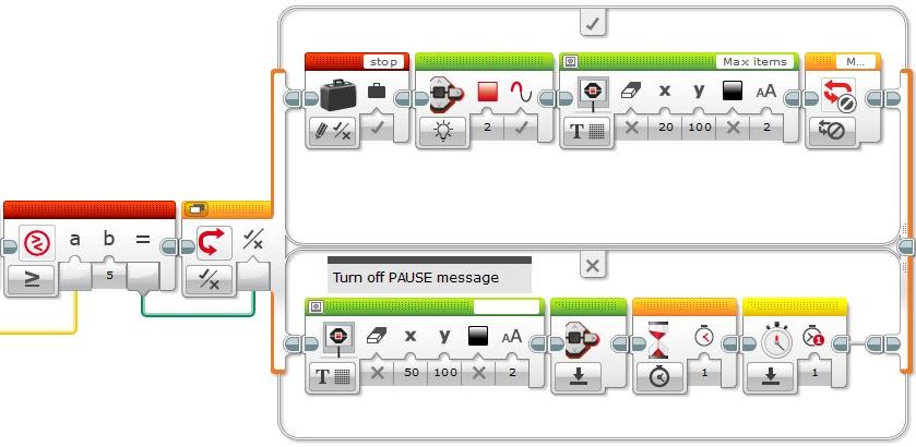
If there are five items of any color, stop the machine, otherwise clear the brick screen message
If the maximum number of items has not yet been reached, the “PAUSE” message is erased and the timer is reset. Why is it important to reset the timer? Otherwise when no color is detected, the sorter machine will stop immediately.
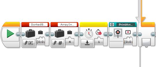
The following image shows the complete sequence of the MasterColor loop program.
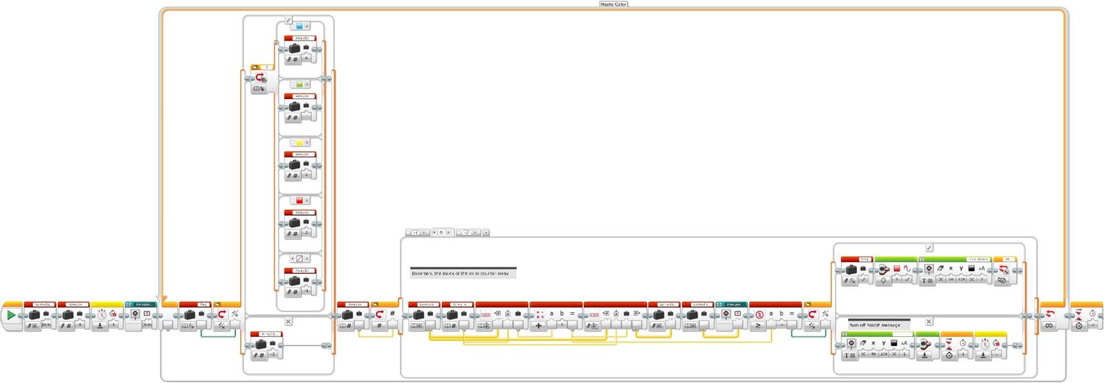
Complete program sequence incorporating the MasterColor loop
The following video shows an example of a color counter sorter machine. To increase the chance of the color sensor reading the color correctly, the slave loop has been modified so that each each item is held under the color sensor for a second.
Acquired knowledge: With this unit students will learn how to use a Touch sensor to control a motor or a main program. They will also learn how to add more conditions and control the flow of the program using different programing techniques and their implications when using Wait, Switch or Loop blocks, and specific strategies to synchronize different programing flow sequences, using variables and the Master/Slave design pattern, which can be very useful to complement the State Machine architecture, studied previously. The students will also understand how to use loops that need to run at different rates and the use of variables and timers to control these loops. Finally, they will learn how to use and operate with arrays and how to display messages and control the status light of the brick screen.
You can also find this learning unit at the legoengineering.com webpage.
![]()
![]()
![]()
![]()